Johnny's home-built CPU corner (and other stuff, maybe)
Description of the XBUS
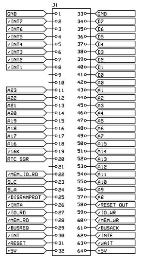
Clock in the image to the right to see a larger picture of how the XBUS are constructed.
Data lines (D0-D7) and address lines (A0-A15) doesn't need any deeper description, so I leave them out for now.
Pin 58 - /RESET signal out from the 8080, active low. Reset logic are placed on the 8080 CPU.
Pin 59 - /IO_WR
Pin 60 - /MEM_WR
Pin 61 - /BUSACK output from the 8080 when it has acknowledged a BUSREQ signal.
Pin 62 - /INTE output from the 8080 telling INTERRUPT flag has been are activated.
Pin 63 - /WAIT input, open collector. When low the 8080 stops as long the /WAIT signal are pulled low.
Pin 2-8 - INTERRUPT lines. They will be connected to an interrupt handler before going into the 8080 (has only 1 INT line).
Pin 11-18 - A16 to A23 used for bank switching. The third 16K of 64K ($8000-$BFFF) can be bank switched.
Pin 19 - /16K Active low when A0-A15 addresses anywhere inside the third 16K block to signal any bank memory to activate.
Pin 20 - RTC SQR - Reserved for a RTC module that can send out clock pulses between 1Hz up to 32.768Hz.
Pin 22 - /MEM_IO_RD are a OR-ed signal from /MEM_RD and /IO_RD used to switch direction on any 74HC243. Hardly used.
Pin 23-24 - SLA, SLC - A future attempt to bit bang any I2C device on the XBUS.
Pin 25 - /DISRAMPROT A write protection for the first 2K/4K of RAM/FRAM memory. Open collector, pull low to write to memory.
Pin 26 - /INTA output from the 8080 to signal an interrupting device.
Pin 27 - /IO_RD
Pin 28 - /MEM_RD
Pin 29 - /BUSREQ input to the 8080, open collector. Signals that a XBUS board want controll over the XBUS.
Pin 30 - /INT input to the 8080. This is the actual interrupt line. See pin 2-8 above.
Pin 31 - /RESET input to the 8080, open collector. When pulled low, the 8080 does a cosl reset, and also pulls down pin 58.
Pin 9, 10 and 21 are free and might be later on be used to explore a SPI interface, like pin 23,24 for the I2C interface.
Pin 25, /DISRAMPROT, can be de-activated under software control by OUTPUT $FF to IO port $FF. By sending $00 to IO port $FF, or by issuing a RESET, the write protection can be activated again.
Homebuilt CPUs WebRing
Join the ring?
To join the Homebuilt CPUs ring, drop Warren a line, mentioning your page's URL. He'll then add it to the list.
You will need to copy this code fragment into your page (or reference it.)
Note: The ring is chartered for projects that include a home-built CPU. It can emulate a commercial part, that′s OK.
But actually using that commercial CPU doesn′t rate. Likewise, the project must have been at least partially built: pure paper designs don′t rate either.
It can be built using any technology you like, from relays to FPGAs.
