Johnny's home-built CPU corner (and other stuff, maybe)
The NOT gate - the basic "thing" that all other "things" is based on.
In it's simplest form the NOT gate, or inverter, is constructed by one transistor, one diod and two resistors. However, there is a flaw with that design and to solve that, one has to add at least one extra diod and one extra resistor. And perhaps one capacitor as well, to help speed up switching times.
Or, one can cheat a little and skip those extra parts, hoping for the best.


This is the basic NOT-gate. The transistor is BC547B / BC548B.
I have also tried 2N3904 with more or less exact same result.
In my LTSpice simulations a HF transistor such as BF199 or BFR93A gives superior result, but, in real life they perform more or less the same as the cheap BC547B. I'm testing on a breadboard and I think there is unwanted capacitances here and there, spoiling the results.
Lately I have been using a lot of SS9018. It is now my #1 choise for "high" speed circuits. Otherwise I use BC547A instead of BC547B. The A-version is a little bit better than the B-version. It has to do with the Miller effect and the transistors hFE. Lower hFE is better here.
The diode is 1N4148. The resistors is a compromise between performance and power usage.
As I said earlier, there is a flaw with this design. The voltage drop over the diode and the transistors BE is more or less the same, giving no room for error. The input swing is only about 0.1 volt and that makes this NOT gate sensitive to noice.
By replacing the input diode from a silicon one to a schottky one, there is a huge (relatively) improvement.
Using a silicon diode, the useful input swing between 1 and 0 is around 0.1 volt. With a schottky diode, that swing goes up to around 0.4 volt.
There is still noice in the picture, but without adding more components I find this version of a NOT gate acceptable for my use.
All my gates use BAT42 as input diodes. I have tried other types but the BAT42 gives the best result.

Measuring at the base of transistor Q1. The input signal comes from a 74HC-output - 50/50 1MHz.
The left image shows the effect of using a 1N4148 as input diode and the right one a BAT42.
At this point a schottky-diode wins!

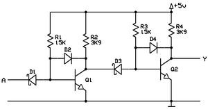
This is my final version of a NOT gate.
By adding a 1N4148 [D2] between the transistors base and collector, the transistor is prevented from going into saturation.
In a real TTL-gate, D2 would be a schottky diode as well, together with the transistor Q1 forming a schottky-transistor. And there would be a lot more transistors and resistors.
By clamping the transistor with D2, the collector do not go down all the way to 0-ish volt. Instead, D2 rises the lowest point to about 0.1 volt. That reduces the input swing to the next stage by the same amount, shrinking 0.4 volt to "only" 0.3 volt.

Now, for further testing I'm using 2 NOT-gates in series, taking measures from the second gate.

One can clearly see the impact on the output signal (Q2) by using a clamp over each transistor. I'm going to use this approach for all my constructions.

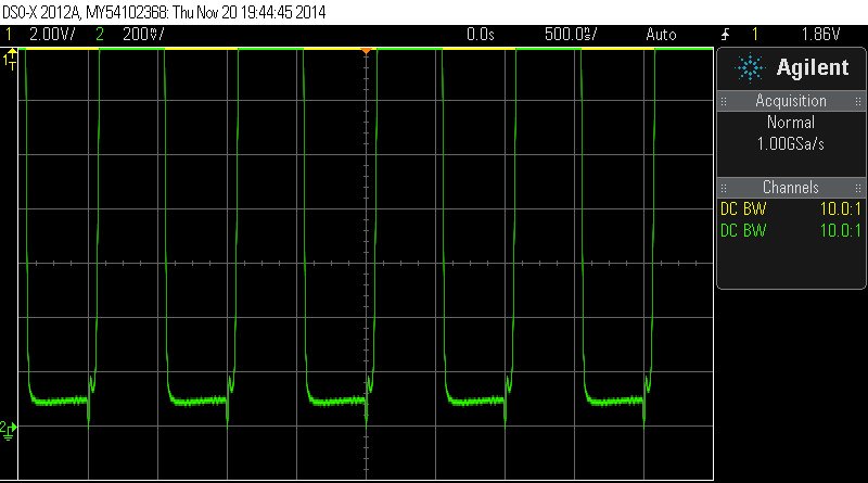
Close up of Q2's collector. Left image: No clamps used. Right image: Clamped with 1N4148.
The clamp prevents the transistor to fully saturate, resulting in a more 50/50-ish output signal than without clamping
Now we can build more complicated gates.


By adding more input diodes we get a NAND gate.
You can add as many input diodes as you want (within reason).
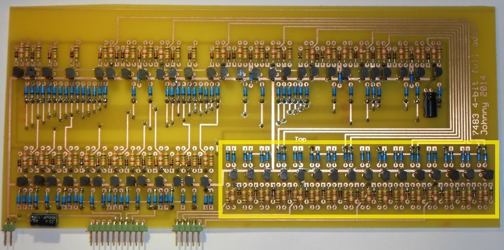
So far the most number of diodes I have used is 5, in my 7483 circuit.
AND gate adds one extra transistor, a NOT gate following the NAND gate. Notice that the added NOT gate is not an fully ordinarily NOT gate. There is no base resistor for transistor Q2 and no input diode either.
NOR gate is constructed by a bunch of NOT gates with their collectors wired together, sharing a single collector resistor.
OR gate?. Just add a NOT gate to the NOR gates output.
XOR gate is a compound gate. There is more than one solution for this complex thing. I believe the one using 4 NAND-gates is the easiest to implement with transistors.
I have marked 4 XOR-gates on my 7483 circuit below. It's only 4 gates but they take up a lot of space.